Chapter 6Analysers
This chapter is for the support technician and the instruments engineer. It explains:
- How an analyser's results reach the program.
- How an analyser is added and linked, and how its codes are mapped to the catalogue's tests.
- How the link is checked, and what to do when results do not arrive.
6.1 How results arrive
No separate program is installed for analysers. The station inside the program itself serves them, the same station that prints (see 7.1 How the program prints). Each analyser has its own worker inside the station, so one analyser never holds up another.
Which computer serves the analyser?
- A network analyser is served by the server, unless another computer is chosen for it. An analyser connects to one address, so the member computers do not all open a port for it at once.
- A serial analyser is served by the computer its cable is plugged into. It is ticked on that computer's station, under Analyzers cabled to this station in the Stations and printers tab. An analyser belongs to one station, so ticking it on one takes it from any other.
- A member computer serves only what was ticked to it.
Ways of connecting:
| Way | What happens | What the card needs |
|---|---|---|
| Network, the laboratory listens | The analyser connects to the station and sends its results. This is the default | Network port, by default 2575. Each analyser has its own |
| Network, the laboratory calls | The station connects to the analyser, and connects again if the link drops | The analyzer's network address and its port |
| Network, the analyzer sends a datagram (UDP) | The analyser sends each result as one message and waits for no answer | UDP port the analyzer sends to, by default 20035. The analyser's address is required |
| Serial port | A cable between the analyser and the station's computer | Serial port, Line speed, Data bits, Parity, Stop bits and Flow control. By default 9600, 8, No parity and 1, with no flow control |
| File folder | The analyser exports its results as files to a folder, and the station reads the folder every two seconds | The folder the analyzer exports its results to. Each file read is moved to the processed subfolder |
Protocols: ASTM (E1381 and E1394), HL7 in an MLLP envelope, TEXT and CSV with a template describing the message, and POCT1-A. POCT1-A does not run on a serial port. The program chooses the protocol from the maker and model (From the maker and model), and the technician may change it.
6.2 Adding an analyser
The page opens from the Settings menu, then Devices and printers, then the Analyzers tab. Changing it needs the Manage devices permission.
- Press Add an analyzer.
- Under The analyzer: type the Analyzer code and the Analyzer name, and choose the Maker, the Model and the Department.
- Choose the way of connecting, and type what the table above asks for.
- Set, when needed:
- Character encoding and Message envelope.
- Where the sample number is in the message.
- Waiting times: leave them empty to keep the standard's times, and fill them in only when the analyser's manual says otherwise.
- Under Results, decide whether the analyser's results are approved automatically: This analyzer's results are approved automatically when they pass every approval check.
- Under Alert, type the Minutes of silence before the alert while work waits (0 switches it off).
- Press Save.
The analyser then shows the page What to type in the analyzer's LIS settings. It gives the address of the computer that serves it, its port, and the line and protocol settings, as they are typed into the analyser's own menus. Beneath it come The analyzer's guide: what to set in its menus, Where a link usually stumbles and How to check once it is set: this model's guide if the library has one, otherwise the general guide of its protocol. A guide not yet tried on a real analyser carries a mark saying so.
A label with a Code 39 check character. If the laboratory's label carries a check character, the program verifies it when the analyser sends the number back, then removes it. About one number in 43 has a space as its check character, so the label ends in a blank. Some analysers send that blank back and some trim it, and the program finds the tube either way. A wrong check character is refused. Two blanks or more at the end are padding, not a check character.
6.3 The firewall and the network
A network analyser needs a rule in the Windows firewall on the computer that serves it:
- Press Open the port in the firewall on the analyser's card.
- On the computer that serves the analyser, accept Windows' request within two minutes.
A rule is added for this analyser alone, in the group Clarus LIS analyzers (see A.4 Firewall rules).
The port is opened to the analyser's address alone when the card has one. Otherwise it is opened to the networks the laboratory declared. A UDP port is never opened without the analyser's address, because the sender's address in a UDP message can be forged.
6.4 Mapping the analyser's codes to tests
The analyser sends each result under its own code. No result is filed until its code is mapped to a test of the catalogue.
From the Clarus library. The Library tab holds ready link files, each with the maker, the model, the way of connecting and the table of codes. Each file carries its evidence:
- Tried on a real analyzer.
- Written from a document — review it.
- Choose the file and press Take it.
- Choose the analyser it applies to.
- Press Review what it would change. What would be added and what would change are shown.
- Press Apply these codes.
Codes can differ between laboratories. Check the review against your own analyzer before releasing results through it.
If the library cannot be reached, opening a link file the laboratory holds always works: Open a link file. Likewise Save the link file saves the analyser's link to a file, for a matching analyser or as a backup. A link file carries no patient data.
By hand. The Test codes tab holds every code the analyser has sent, with those that arrived Not mapped first. Choose the code, press Map it to a test and choose the test. One code may mean several tests: «Map it» changes its test, «Add it too» keeps it and adds this one, and a result lands on whichever the tube carries.
6.5 Checking the link
On the analyser's card:
- Test the connection: the station connects to the analyser, or opens its port, and says whether it reached it.
- Test message: a message is pasted as the analyser sends it, and handled as if it came from the analyser. It tries the whole link before the analyser has sent anything.
- The link now: whether the link is open and since when, the last message, how many were received and held today, and The station serving it.
- Link log: every connection, disconnection and error, with its time.
- The analyzer's messages: the incoming and outgoing messages as they are, Patient data hidden or Complete. A message that was not filed carries its reason as a sentence in the program's language, not the analyser's code.
- Held messages: what the analyser sent that was not filed, each with its reason. Fix the reason, choose the rows and press Process again.
6.6 Three worked examples
Three analysers, one for each way of connecting. Each maker's own document says how its analyser connects. What is typed on the analyser's side is said here in general terms: the names of its menus are in its maker's manual.
6.6.1 A network analyser speaking HL7: Roche cobas pro
Roche's technical specification of cobas pro gives it a host connection over the network with HL7.
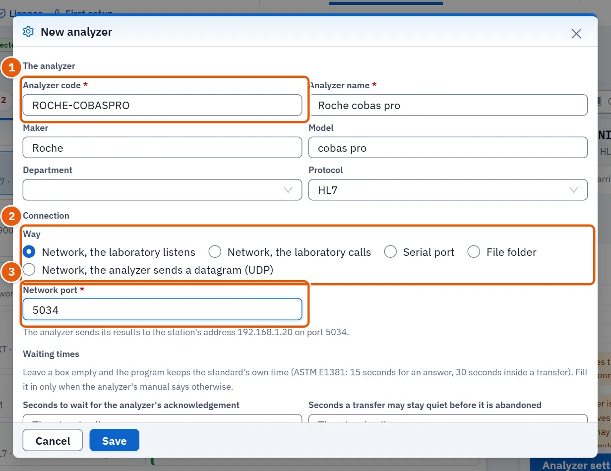
- Press Add an analyzer.
- 1 Type the Analyzer code
ROCHE-COBASPRO, the Analyzer name, the MakerRocheand the Modelcobas pro, and chooseHL7as the protocol. - 2 Choose Network, the laboratory listens.
- 3 Type the Network port:
5034. Each analyser has a port of its own. - Press Save, then Open the port in the firewall (see 6.3 The firewall and the network).
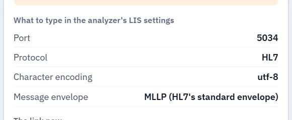
The card then shows What to type in the analyzer's LIS settings: the address of the computer that serves the analyser and the port. On the analyser's side, in its settings for the laboratory system: the host's address and port as the card gives them, the protocol HL7, and sending results to the host automatically.
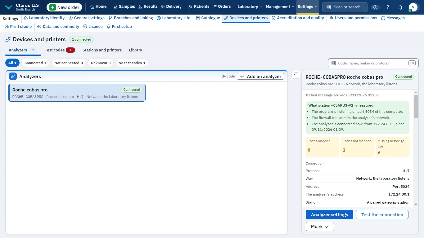
With the analyser set up, press Test the connection: the station on the computer that serves it looks for it, and the card says whether it reached it, from which address, and since when. For a network analyser the card then lists what the station measured: whether the program listens on the analyser's port, whether the Windows Firewall rule admits the analyser's network, and whether the analyser is connected now.
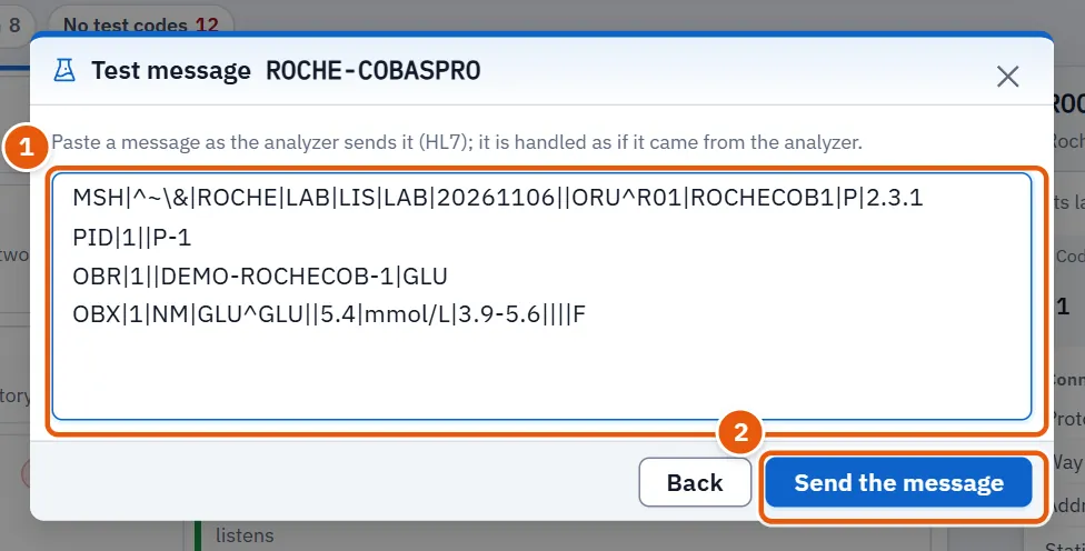
To try the whole link before the analyser has sent anything: More, then Test message.
- 1 Paste a result message as the analyser sends it.
- 2 Send the message records its results as if they came from the analyser. Use it with the number of a test tube only.
Once the analyser sends, each message shows in The analyzer's messages, as it arrived.
6.6.2 A serial analyser speaking ASTM: Stago STA Compact Max
Stago's document of its ASTM protocol connects the analyser over an RS-232 serial line, at 9600 bauds by default, with 8 data bits and no parity.
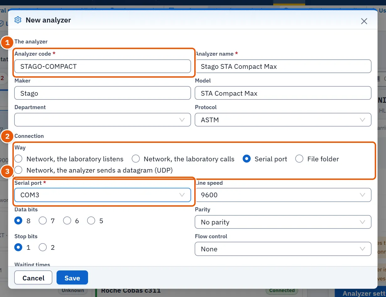
- Press Add an analyzer.
- 1 Type the Analyzer code
STAGO-COMPACT, the MakerStagoand the ModelSTA Compact Max, and chooseASTM. - 2 Choose Serial port.
- 3 Choose the Serial port the cable is plugged into, here
COM3, then Line speed 9600, Data bits 8, Parity No parity and Stop bits 1. The list holds the ports the stations report; an empty list points to the cable or its adapter's driver (see 6.8 When results do not arrive). - Press Save.
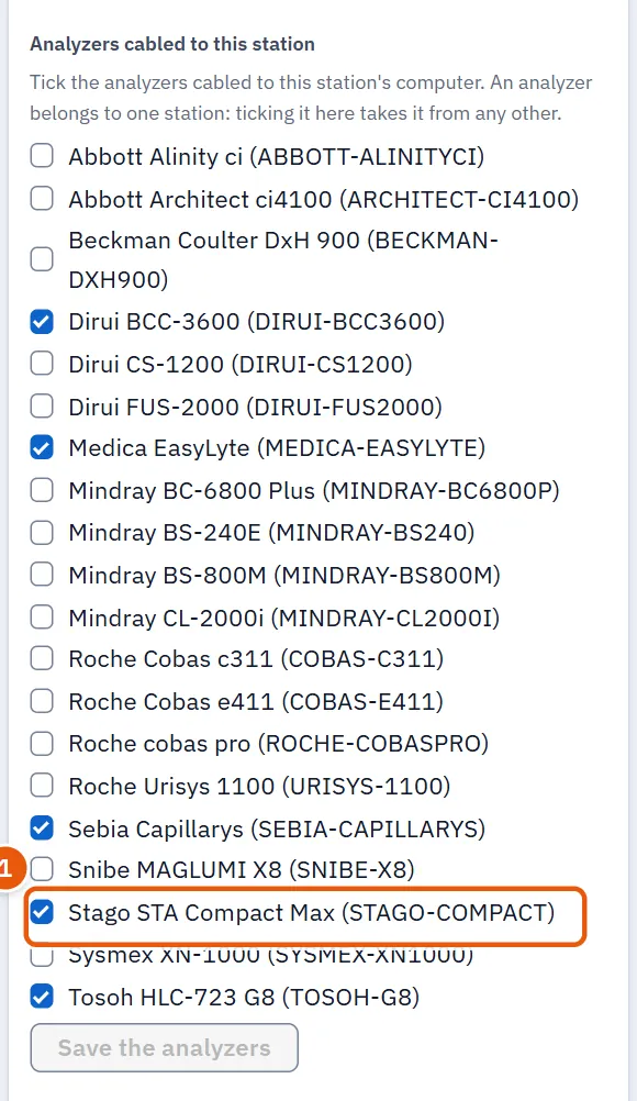
A serial analyser is served by the computer its cable is plugged into. In the Stations and printers tab, choose that computer's station, 1 tick the analyser under Analyzers cabled to this station, and press Save the analyzers.
On the analyser's side, in its settings for the laboratory system: the same line settings as the card (speed, data bits, parity and stop bits), the protocol ASTM, and sending results to the host automatically.
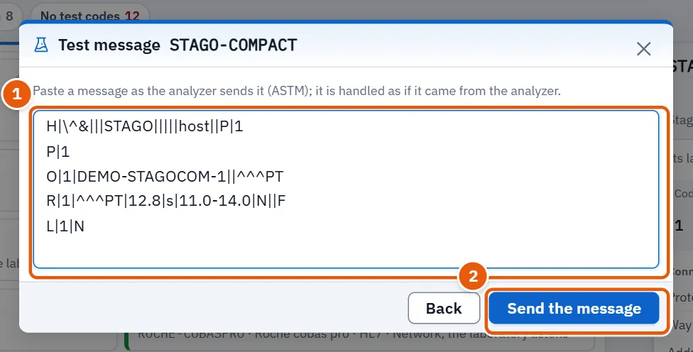
The test message is pasted as the analyser sends it, its records one per line, as in the HL7 example: 1 the message, 2 Send the message.
6.6.3 An analyser exporting files: Sebia Capillarys 3
Sebia's document of the PHORESIS host module lists, among its ways of connecting to the laboratory system, exchanging files. The analyser writes its results into a folder, and the station reads that folder.
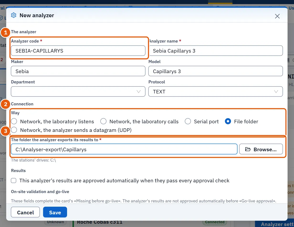
- Press Add an analyzer.
- 1 Type the Analyzer code
SEBIA-CAPILLARYS, the MakerSebiaand the ModelCapillarys 3. - 2 Choose File folder.
- 3 Type the The folder the analyzer exports its results to, or press Browse to choose it.
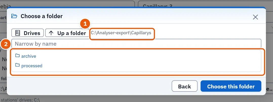
Browse opens the folders of the computer whose station serves the analyser, not those of the computer in front of you: 1 where you are, 2 its folders. Open the folder the analyser exports to and press Choose this folder.
The file's layout is not published in what was found for this analyser, so the example stops here: until the layout is set, the card says This analyzer's file format is not set yet, so its files will not be read: set it under «Results files» below the card. The layout is written from the maker's description of its result file.
On the analyser's side: export the results as files to the same folder, shared with the station's computer if the analyser's own computer is another.
6.7 Both directions: work orders
With Both directions chosen, the analyser takes from the program what to run on each tube, in one of two ways:
- The analyser asks about the tube when it reads the barcode. How the analyzer asks about a tube is chosen: ORM^O01, QBP^Q11, or QRY^Q02 with DSR^Q03.
- The program sends work orders as tubes arrive: Send work orders to the analyzer automatically as tubes arrive, with the Work-order message: ORM^O01, OML^O21 or OML^O33.
Both directions work only with HL7 and ASTM, never with files. The Work orders screen shows what was sent to each analyser, what came back, and what was not filed and why.
6.8 When results do not arrive
| What shows | Likely cause | What to do |
|---|---|---|
| No station serves this analyzer now: run the program on the computer it is connected to. | The program is not running on the computer that serves the analyser | Sign in to Windows on that computer (see 4.3 How the program starts) |
| No station has been marked as cabled to this analyzer yet: tick it on its station in «Stations and printers». | A serial analyser not ticked on any station | Tick it on the station of the computer its cable is plugged into |
| No station has reported a serial port yet. Plug the cable into the station's computer, then open this window again. | The cable is not plugged in, or the USB adapter's driver is not installed | Plug in the cable, install the adapter's driver, then open the window again |
| Waiting for the firewall rule | No firewall rule | Open the port in the firewall, and accept Windows' request |
| The permission request lapsed: ask again or The permission was refused: ask again | Nobody accepted Windows' request in time | Ask again, and accept it on the computer that serves the analyser |
| A warning that the network is Public | Windows classes the network as Public | The computer's administrator makes it Private, as above |
| The port is taken | Another program, or another analyser in the program, uses the port | Choose another port, and type it into the analyser too |
| A shared port needs the analyzer's address | Two analysers on one port | Type each analyser's address on its card |
| The analyzer could not be reached | The analyser's address is wrong, the analyser is off, or it is on another network than the computer | Check the address and the cable, then Test the connection |
| The folder is missing | The export folder does not exist on the station's computer | Create the folder or correct its path |
| This analyzer's file format is not set yet, so its files will not be read: set it under «Results files» below the card. | The analyser's file format is not set | Set it as the message says |
| The link is open, no results, and the messages are in Held messages | An unmapped code, or a sample number the program does not know | Map the code, or correct Where the sample number is in the message, then Process again |
| Strange letters in patients' names on the analyser | The encoding does not match the analyser | Correct the Character encoding |
| The link drops in the middle of a transfer | The times are shorter than the analyser needs | Set the Waiting times as the analyser's manual says |